I’ve been building Raspberry Pi NTP servers ever since the first Raspberry Pi became available. Each time I complete one, I think that the next one I build will be the final one. I think I’ve built at least 5 previous models. I’ve built really basic ones, and some with built in clock displays. I’ve used a variety of chipsets for GPS, including Garmin GPS-16X puck receivers, the Adafruit GPS Hat, various Sparkfun chips, etc.
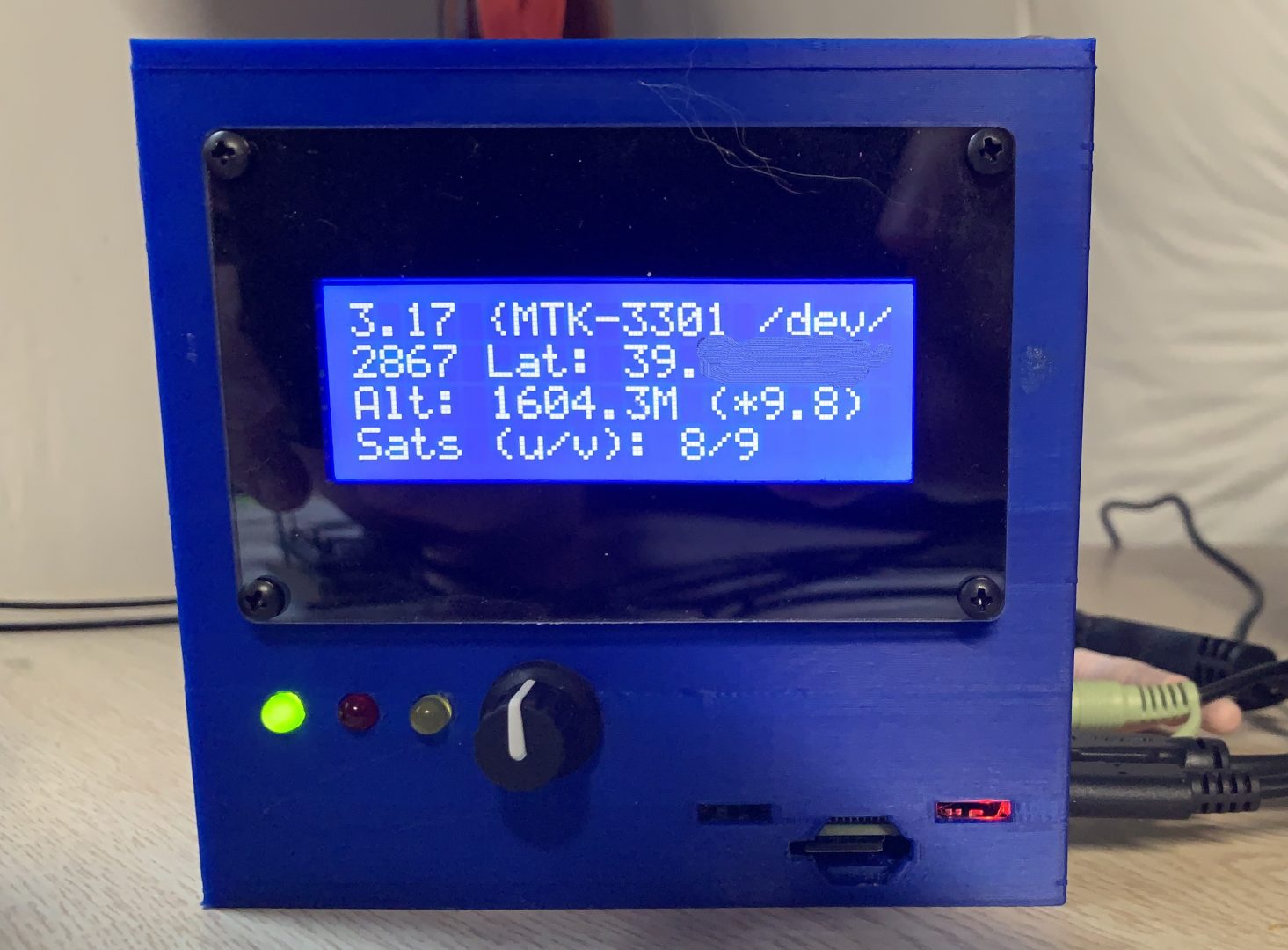
My latest effort is to improve the management/ease of use. In this series of blog posts, I’ll go over some of the neater things that were in this one. The picture shows the completed project.
This NTP server adds some pretty neat features.
- Monitoring service that watches parameters like NTP offset, CPU Utilization, etc. Additionally, the monitoring service provides the informational screens to drive the LCD display.
- Alarm LED, If a limit is exceeded, a red LED is flashed, indicating alarm state.
- A PPS indicator on the front of the case. This provides a continuous indication that the GPS signal is locked.
- An LCD Display to show status screens. In total, there are 5 screens:
- Clock/NTP Info, real-time clock, NTP peer name, NTP Packets, offset and Jitter
- GPSD Info including latitude/longitude, altitude, and used/visible satellites.
- System load information including CPU, Load, RAM, and uptime.
- Network interface information including IP Address, and transfer statistics.
- Raised Alarms Screen
- Raspberry Pi information including chipset/revision information.
- A rotary switch for selecting the active information screen.
- Use of Grafana for monitoring NTP, the Raspberry Pi, and GPSD.
In future posts, I’ll give more details about the creation of the system. I’ll cover:
- Creating the case using 3D CAD software and a 3D Printer
- The benefits of using Go for the project. Go offers some really nice features for managing concurrency that made this much simpler.
- Interfacing the Adafruit I2C/SPI LCD Backpack Display
- The Hell of Rotary Switches
- Creating an alarming subsystem for managing LEDs, logging, etc..
- Reading NTP Data using NTPQ
- Reading GPSD Data
- Using Grafana for Monitoring